
I have read several posts to reduce the power consumption of micro-controllers and learned that the althought you can minimize the power consuption of arduino, usually you have other sensors/chips that cosume more power then customized low power arduino.
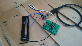
The idea now is to use ATtyni13A – Atmel picoPower 8-bit AVR RISC-based microcontroller as a timer switch for the all other circuits especially for projects, when you want your circuit run once an hour or less for only some seconds (data loggers,..). In this case the ATtyni13A is up and running 24/7 and everything else is without the power, so the consumption of the rest of the circuit is 0A. ATtyni13A consumption is only 0.005mA (5µA) in a sleep mode.

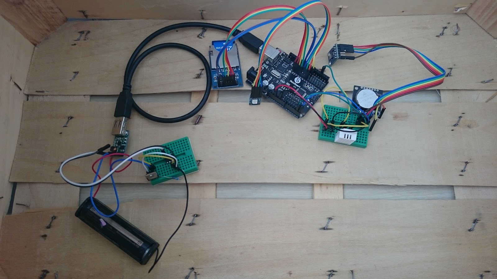
As you can see, ATtyni13A is used only as a controller of 1 N-channel MOSFET, that is turning on/off 5V booster for the Arduino UNO plugged with standard USB cable. For the tests used in this post I have used LED to measure power consumption instead of MOSFET. I have used these low power concept in my projects:
- Battery Powered ESP8266 IoT – Door Sensor
- Battery Powered ESP8266 IoT – Temperature and Hunidity DHT22 Sensor
Check my other post that describes how to program ATtyni13A via Arduino board.
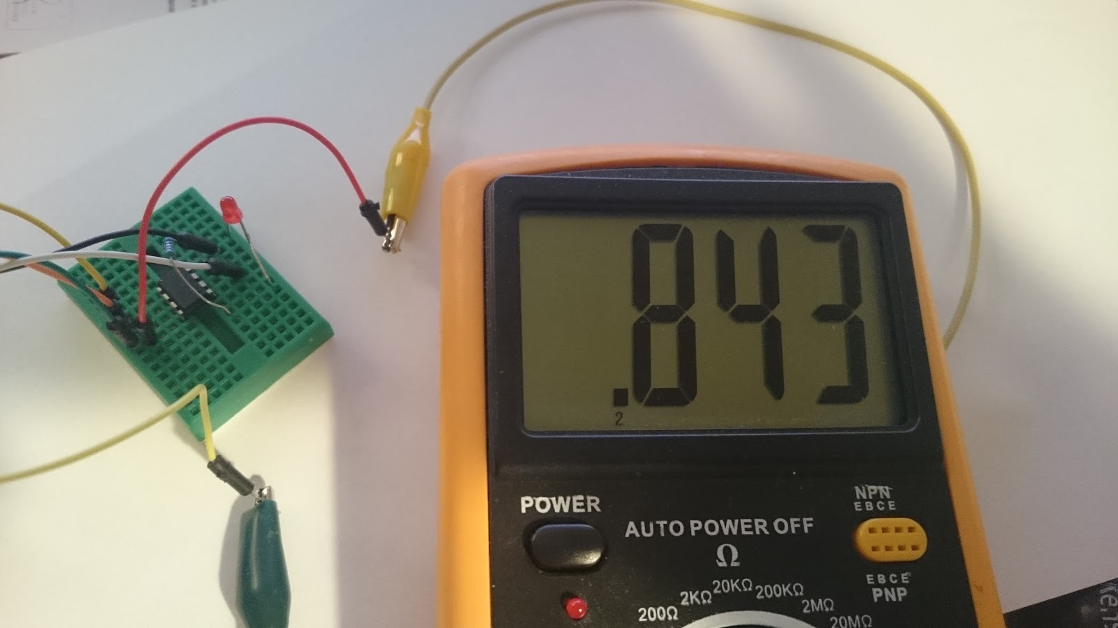
So what is the ATtyni13A power cunsuption?
The consumption of ATtyni13A in up time mode without any circuit is really low, less then 1mA. In my case my multi-meter showed 0.843mA powerd by 3.3V.
Low power ATtyni13A in sleep mode and interrupt
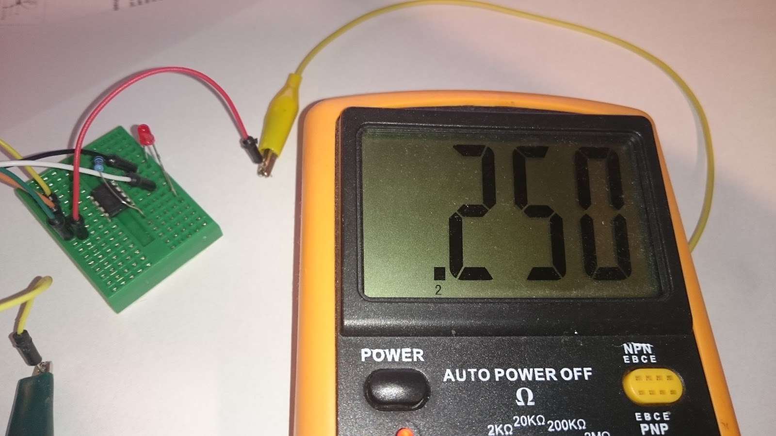
Less then 1mA is good but with just simple program changes (sleep and interrupt) we can get with power consumption during the sleep time even lower.
This code will wake up ATtiny13A every 8s and turn the LED on for 1 sec.
#include <avr/interrupt.h>
#include <avr/sleep.h>
// Pin 4 for LED
int led = 4;
ISR(WDT_vect) {
	digitalWrite(led, HIGH);   // turn the LED on (HIGH is the voltage level)
	delay(1000);               // wait for a second
	digitalWrite(led, LOW);    // turn the LED off by making the voltage LOW
	sleep_mode();
}

void setup() {
	// initialize the digital pin as an output.
	pinMode(led, OUTPUT);
	// prescale timer to 8s so we can measure current
	WDTCR |= (1<<WDP3 )|(0<<WDP2 )|(0<<WDP1)|(1<<WDP0); // 8s
	// Enable watchdog timer interrupts
	WDTCR |= (1<<WDTIE);
	sei(); // Enable global interrupts
	// Use the Power Down sleep mode
	set_sleep_mode(SLEEP_MODE_PWR_DOWN);
	for (;;) {
		sleep_mode();   // go to sleep and wait for interrupt...
	}
}
// the loop routine runs over and over again forever:
void loop() {
}
The current during the sleep mode is 0.250mA.
Disabling ADC controller of ATtyni13A
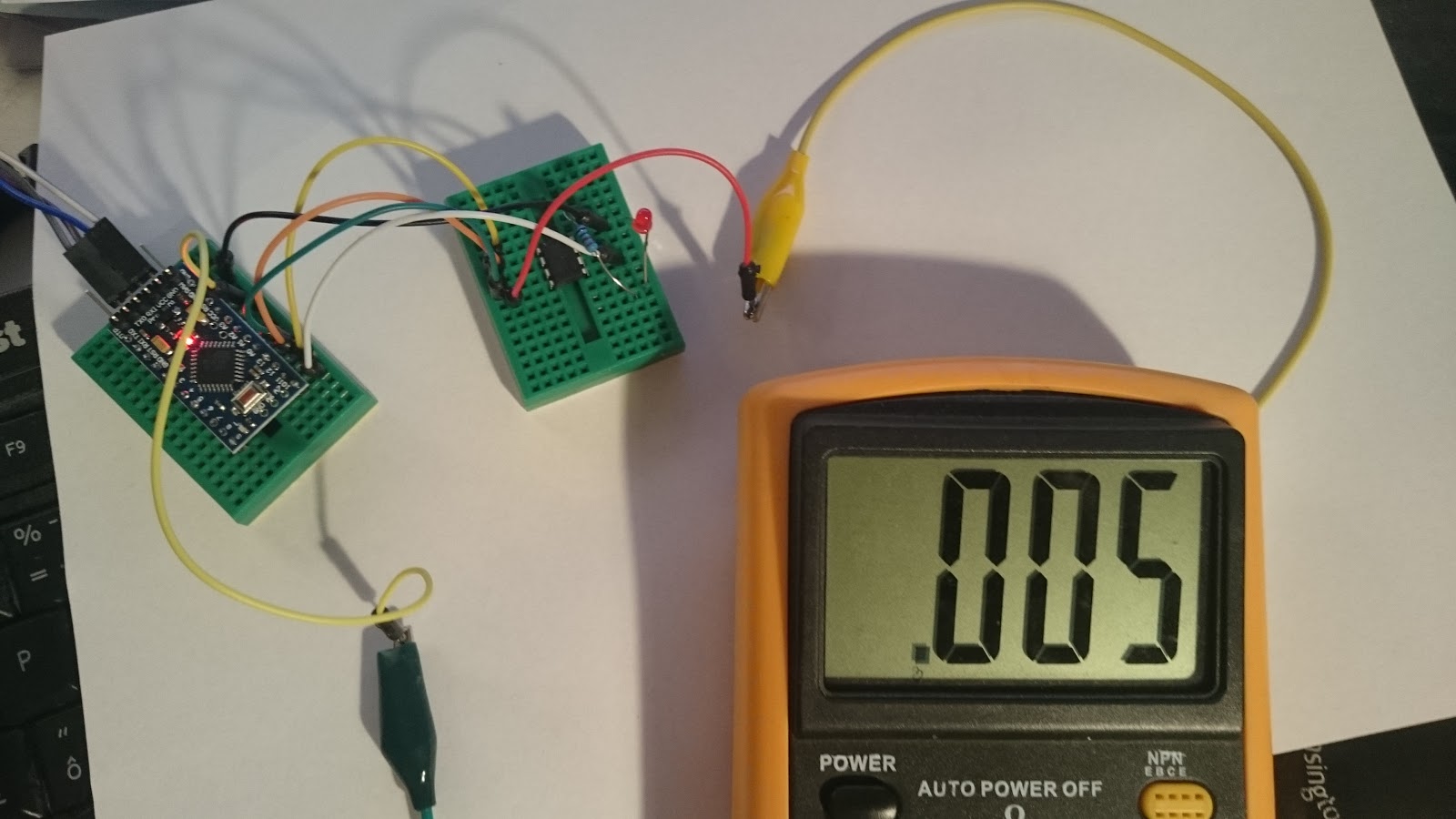
By disabling the ADC converter in ATtyni13A we can go even lower! Add the following line to turn the ADC off on ATtyni13A:
ADCSRA &= ~(1<<ADEN)
To enable it, if you use ADC during the ATtyni13A uptime just put this line:
// initiate conversion
ADCSRA |= (1 << ADSC);
// wait for completion
while (ADCSRA & (1 << ADSC));
By turning off the ADC converter we can go down to 0.005mA with 3.3V! This is lower then was my expectations at the begging.
Other Hints
The line:
WDTCR |= (1<<WDP3 )|(0<<WDP2 )|(0<<WDP1)|(1<<WDP0); // 8s
is setting the timers configuration and 8s is the max Other values are listed:
16MS   (0<<WDP3 )|(0<<WDP2 )|(0<<WDP1)|(0<<WDP0)
32MS   (0<<WDP3 )|(0<<WDP2 )|(0<<WDP1)|(1<<WDP0)
64MS   (0<<WDP3 )|(0<<WDP2 )|(1<<WDP1)|(0<<WDP0)
125MS  (0<<WDP3 )|(0<<WDP2 )|(1<<WDP1)|(1<<WDP0)
250MS  (0<<WDP3 )|(1<<WDP2 )|(0<<WDP1)|(0<<WDP0)
500MS  (0<<WDP3 )|(1<<WDP2 )|(0<<WDP1)|(1<<WDP0)
1S     (0<<WDP3 )|(1<<WDP2 )|(1<<WDP1)|(0<<WDP0)
2S     (0<<WDP3 )|(1<<WDP2 )|(1<<WDP1)|(1<<WDP0)
4S     (1<<WDP3 )|(0<<WDP2 )|(0<<WDP1)|(0<<WDP0)
8S     (1<<WDP3 )|(0<<WDP2 )|(0<<WDP1)|(1<<WDP0)
If we need timer for more then 8 seconds we will just introduce the counter of 8s. E.g. timer for 2min would be:
int count = 0;
int led = 4;
ISR(WDT_vect) {
	count = count +1;
	if (count > 15) // if interrupted 15. times ( after 15*8sec = 120s = 2min )
	{
		digitalWrite(led, HIGH);   // turn the LED on (HIGH is the voltage level)
		delay(1000);               // wait for a second
		digitalWrite(led, LOW);    // turn the LED off by making the voltage LOW
		count = 0;
	}
	sleep_mode();
}
This method is very useful if the up time of the circuit behind the ATtyni13A is lower then 8s. I have used Arduino UNO dataloger sample that needs ~4 sec to measure and then it is completely turned off by N-channel MOSFET controlled by ATtyni13A. I have used 1 battery and 5V power booster that supply the Arduino UNO via USB cable.
Other related posts
Read the low power circuit post if you are interested in simple disconnecter circuit controlled by arduino.
——————————–
other tips you can google:
ADCSRA &= ~(1<<ADEN); //Disable ADC
ACSR = (1<<ACD); //Disable the analog comparator
DIDR0 = 0x3F; //Disable digital input buffers on all ADC0-ADC5 pins.
Battery Life Calculator
High pulse drain impact on CR2032 coin cell battery capacity
Coin cells and peak current draw. Protection by capacitor
Instead of using N-channel MOSFET to source power from battery, why not use a P-channel MOSFET?
N-channel will have a VGS drop at your output
I have used N-channel MOSFET IRL2230 which has Static Drain-to-Source On-Resistance RDS(on) 10mOhm. So with 200mA it is 2mV drop. I assume it is not relevant in voltage 3.0-4.5V and is occurring only during MOSFET is saturated.
IRL2230 specs: http://www.infineon.com/dgdl/irl2203n.pdf?fileId=5546d462533600a40153565b549324f9
That is the reason I have stopped using 2N7000 for higher current which has RDS(on) 6 OHM (that would be 1.2V).
Please comment if my assumptions are not OK. 🙂
thanks
Many thanks for this post, which I found while investigating ways of running nodemcu wifi modules on batteries. Based on my experience with that project, I’ve written a somewhat more sophisticated program for the attiny13a which:
1. reverses HIGH and LOW for the output pin, as I use a P-Channel MOSFET which needs HIGH for off and LOW for on
2. Moves the control code into the main loop rather than doing real work inside an interrupt routine which I found problematic
3. Ensures that the brownout timer is disabled in the initial bootloader fuse settings ( this makes a huge difference to sleep current 30uA instead of 5uA )
4. Most importantly, after two seconds, rather than turning off, the attiny goes into a loop monitoring pin 3 and waiting till it goes low until it goes back to sleep. That way my power-hungry wifi module can start up, raise a GPIO pin high, and leave it high until it’s finished, however long that takes. That way, I can have the wifi module do clever things based on responses to its posting of information, without worrying about running out of time.
If you are interested, I would be happy to share the code.
I’m very interested in your code! Just ordered some ATtiny13A’s yesterday and going to make power switches of them for multiple projects. Do you happen to also implement any type of battery voltage monitoring? Would be great for ESP8266 projects so you can get a notification on low battery.
Can I request code and engagement? Thank 🙂
staniprokaravany@email.cz
Hi, I’m also interested in your code. I like the idea to wait until ESP finish its job and then send signal to ATTiny to go to sleep. But I can’t figure it out by myself. Thank you. rumczeis ( at ) centrum.cz
I have compilation error:
wiring.c.o (symbol from plugin): In function `__vector_8′:
(.text+0x0): multiple definition of `__vector_8′
/tmp/arduino_build_769301/sketch/sketch_dec03a.ino.cpp.o (symbol from plugin):(.text+0x0): first defined here
collect2: error: ld returned 1 exit status
exit status 1
Could you help me with that?
I believe you figured out this issue already, but for other users I found solution here: https://github.com/MCUdude/MicroCore/issues/23#issuecomment-302899659
Basically you need to comment out line #define ENABLE_MILLIS in core_settings.h, saved in c.a.: c:UsersYOURUSERAppDataLocalArduino15packagesMicroCorehardwareavr1.0.3coresmicrocore