

Since my latest ESP8266 temperature humidity IoT logger project is up and running I have decided to cut the last wire – power. There are more approaches how to make ESP8266 running on a battery, but why not to have a unique one… 😎
The idea is to use only 5µA AtTiny13A (5 microA 2-3V) during the idle time to decouple all other components from batteries! So really 0 power usage from all other components (power regulator, DHT22 sensor,..), since the more components the more idle power consumption. All other circuits should wake up only during limited time and then again turn off.
I have combined knowledge mostly from two my previous projects:
- ESP8266 wifi temperature and humidity sensor on 5V USB power project – see details

- Low power (5microA) ATtiny13A project as a power switcher project – see details


This is my latest version of the wiring that I used:
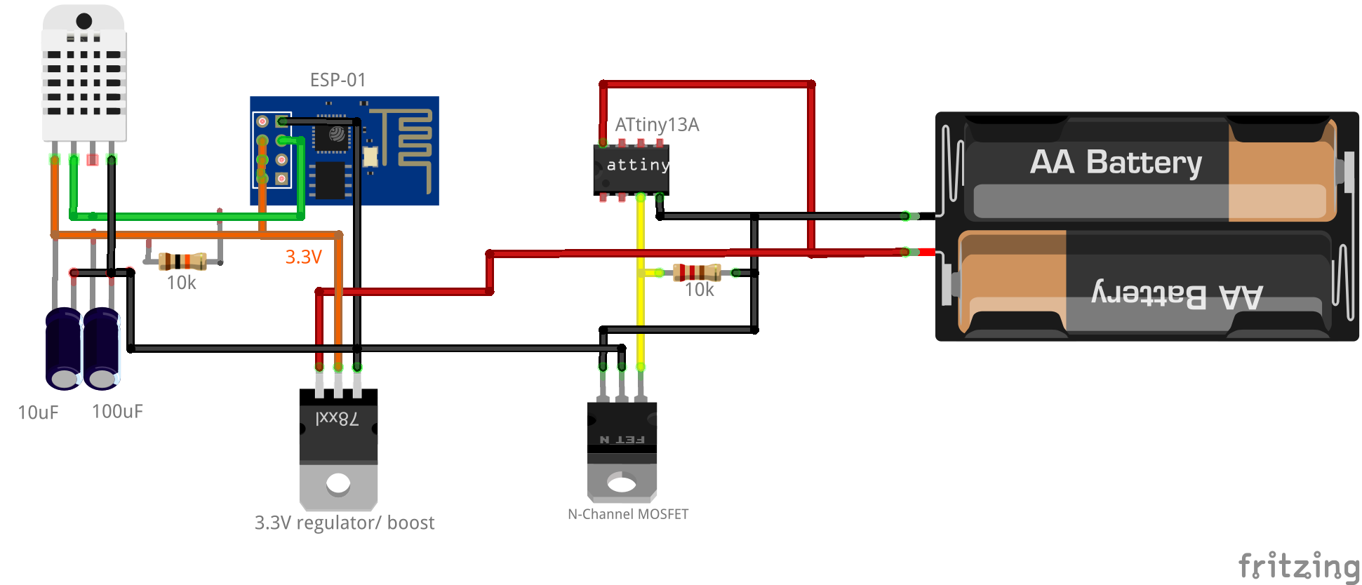
Parts list:
- ESP8266 ESP-01 Wifi Module
- DHT22 with 10kΩ
- 3.3V Voltage Regulator – step up (booster)
- AtTiny13A
- N-channel MOSFET IRL2203N with 100kΩ
- 2xAAA batteries with battery case
My AtTiny13A programmer and ESP01 programmer from my previous posts helped me to easilly program ESP8266 and AtTiny13A:


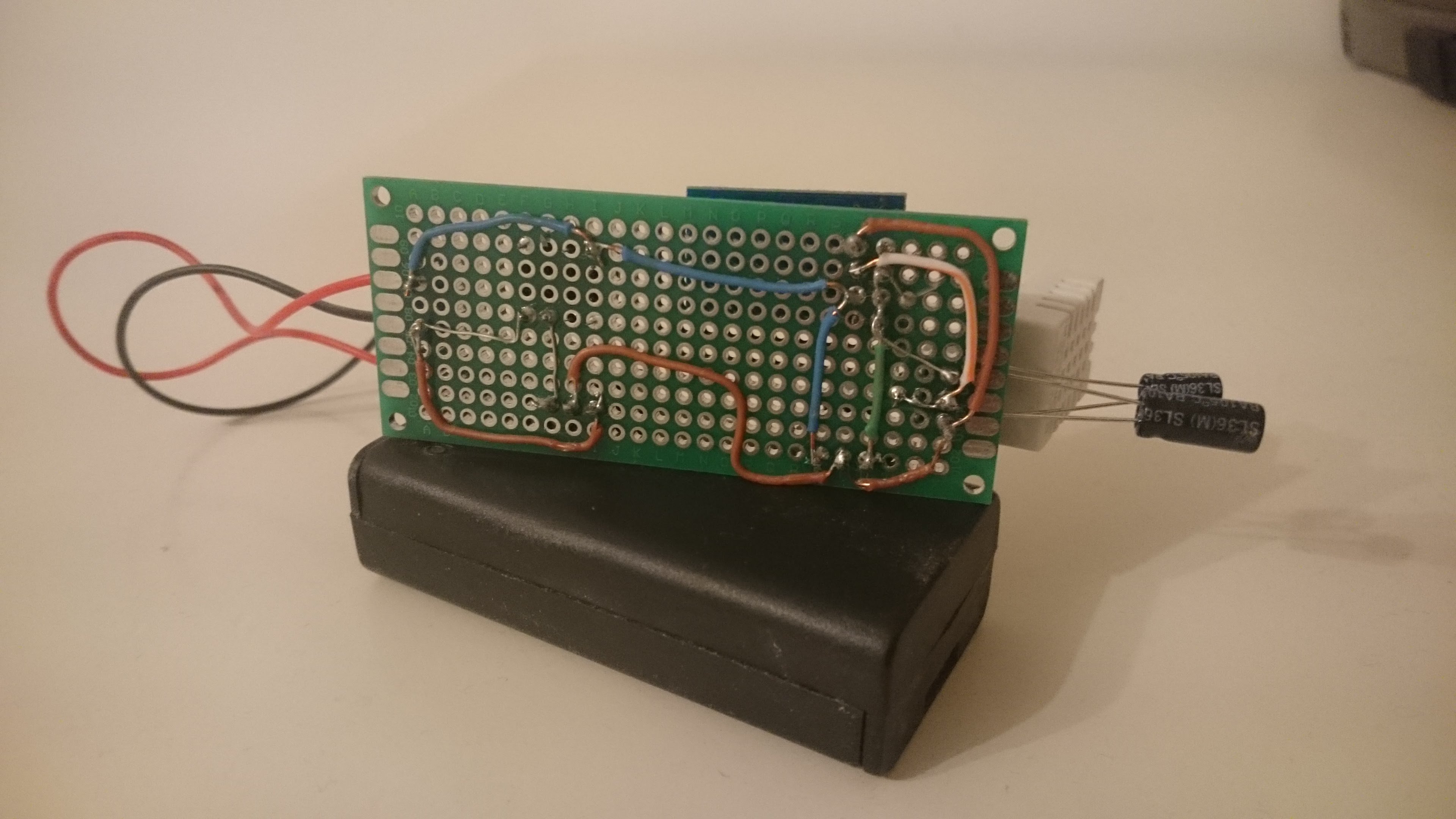
The project is up and running. I used double AA batteries. Sending data every ~20 minutes.:


Updated version with capacitors:

Logs from my server:
{"temp":"24.60","hum":"46.40","voltage":"1023","milis":"4701","datetime":"2016-01-31 16:35:58"}
{"temp":"24.10","hum":"48.90","voltage":"1023","milis":"4794","datetime":"2016-01-31 16:48:38"}
{"temp":"24.00","hum":"49.30","voltage":"1023","milis":"3795","datetime":"2016-01-31 17:09:59"}
{"temp":"23.70","hum":"47.10","voltage":"1023","milis":"4722","datetime":"2016-01-31 17:31:22"}
{"temp":"0.00","hum":"nan","voltage":"1023","milis":"4705","datetime":"2016-01-31 17:52:44"}
{"temp":"23.80","hum":"48.20","voltage":"1023","milis":"5252","datetime":"2016-01-31 18:14:06"}
{"temp":"23.70","hum":"47.90","voltage":"1023","milis":"4738","datetime":"2016-01-31 18:35:27"}
{"temp":"0.00","hum":"nan","voltage":"1023","milis":"4732","datetime":"2016-01-31 18:56:49"}
where:
tempandhumare DHT22 temeperature and hunidity valuesvoltageis raw value from ESP8266 GPIO reading. Should get 0 if not sure which voltage will be provided to this pin. – only experimentalmilisis a ms that ESP8266 needs to send data to the serverdatetimeis added timestamp on the server side
I will do real battery life measurements and I will compare different batteries as power source (AA, AAA, CR2032,..). IoT data logger is configured to send data via wifi every 20 minutes for the test. This post will be continued!
Problems I had to solve:
- Which battery to use – using 2xAA since CR2032 3V nor 2xAAA were not able to power ESP
- DHT22 needs time to get values – waiting 2s after the mosfet is on. In general in these steps: wifi.begin, wait till 2s uptime, read DHT, wait for wifi connect, send data to server, go to the light sleep
- power for N-Channel Mosfet – looks stable from 2xAA
- Step up or step down voltage regulator – I used step-up to squeeze the batteries
- Shorten the ESP8266 connection time (static IP,..) – used static IP and optimized mentioned DHT22 readings
- Read battery level – ESP01 has only GPIO (not ADC). I will add the second ATtiny13A or ATtiny85 to get analog batteries voltage and transfer the digital value to ESP-01 – not implemented now
I will post the source code, once it’s stable and proven.
UPDATE 2016/11/02:
I have stopped using DHT22 because it is slow (2s) and spent lot of time to fine tune the code and still it is not final (although it’s up and running more then 9 months now). The ESP needs to be up for 8s to get reliable data with compare to 4s with SI7021 sensor used in battery-wifi-iot-temp-hum-soil-moisture-sensors.
But anyway the ESP8266 code for DHT22: https://gitlab.com/snippets/30509
ATtiny code to wake up 20min for 8s: https://gitlab.com/snippets/30510
ESP8266 for SI7021 (it reads also data from ATTiny85 serial, that you can remove): https://gitlab.com/snippets/30512
ESP Battery life
2 x Tesco AA batteries
UPDATE: After adding 2 capacitors (100uF and 10uF) in parallel with DHT22 the readings are stable.
After 28 days, the batteries are 2,85V with 1985 temperature/humidity readings.
After 50 days, the batteries are 2.77V with 3544 temperature/humidity readings.
After 3months, the batteries are 2.69V with 4409 temperature/humidity readings
So finnaly after 69days, the batteries are 2.62V with 4655 temperature/humidity readings. So the project works more than 3 months on 2x Tesco AA batteries 😎
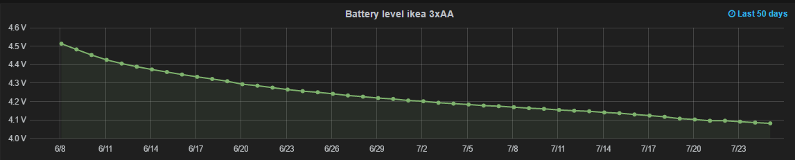
3 x Ikea AA batteries
Check project version with only SI7021 temperature and humidity sensor with 3xIkea AA batteries and with ATtiny85 for battery level measurements.
After 50 days the interim batteries voltage level is 4.08V with WiFi transferring and 4.34V (1.44V each!) during sleep mode. The project is still up and running after 3171 measured and transferred data:
The project is up and running after 21 weeks.
Results
Bellow is a widget combination of all of my IoT data from I2C on my cubieboard, ESP8266 on battery, ESP8266 on USB and also Yahoo data. Also check my another ESP8266 battery IoT door sensor project.

Nice work!
I wanted to try something similar, but with and ATtiny85 and I wanted to readout the DHT with the microcontroller (also powerup/powerdown before powerup ESP). Voltage measurement can – as you suggested – also be done on the micro itself using the internal voltage reference (maybe it should be calibrated before, also raw temperature measurement inside is possible IIRC to compensate the ADC temperature drift) . I wanted to emulate a i2c client device on the tiny as-well, so that I can add more sensors to the ESP-01 module and have an very easy access protocol between the ATtiny85 and the ESP-01. In the end the ESP can send the leave-i2c-command to the tiny and it’ll powerdown. This should save more energy. I often also rework the arduino libraries to squeeze more deep sleep time out of it, but you’ll end up not using any library at all.
a problem I encountered it, that I had to reread the DHT at least once to get a good reading. Did you encounter similar problems?
Andreas
I’m considering also other way: ESP-07 with ATtiny13A and now I have added to my plans your ESP-01 + ATtiny85 combination.
Either use ESP-01 only for wifi and utilize ATtiny85 for i2c/ SPI sensors and timing. Or ESP-07 for wifi/sensors and ATtiny13A only to reduce power. So thanks for sharing your idea.
The reason why I have not posted the code is just because DHT22 reading (I had zero or nan values randomly). I have now DHT22 reading in loop until I have valid number and I send loop count to the server. The count is 1 or 10 (200ms dellay), so adding 2sec uptime in about 50% (but with 100% valid reading value now). So no once but 10 times with 200ms dellay, which corresponds to DHT22 specification 0.5 Hz sampling rate (2s).
As of now my ESP01 uptime is 3778ms to 7340ms (depends on wifi and DHT). After a week my 2 AA batteries went down from 3,2V to 3,05V so it looks promising till now (398 readings).
Regarding the battery reading I have now plans to add one more ATtiny13 powered from voltage regulator (3.3V) so I can directly read batteries (max 3,2V) so I will not have to use voltage divider and internal reference. Or I will just wait for ESP-07 and will read it there. Or as now I just use my multi-meter time to time 😉
Which step up did you use exactly? On Fritzing it says 78xx. Can you be more specific?
I love your idea though! About to build mine as well.
Now I use the very cheap one: http://www.ebay.com/itm/2pcs-DC-1-8V-3V-3-7V-5V-to-3-3V-Step-UP-Down-Power-Supply-Module-replace-AMS1117-/261950171859?hash=item3cfd726ad3
I am testing 3xAA batteries with this step down/up and looks very promising.
With my other project http://homecircuits.eu/blog/battery-wifi-iot-temp-hum-soil-moisture-sensors/ on 3xAAA it went down from 4.6V to 3.7V (1.23V each) in rest and last send value with wifi transmitting was 3.33V (then 3xAAA could not get enough current to power wifi).
Is it really promising? It says the maximum current it can supply is 150mA. The ESP itself only need around 150mA.
I know, but I have two of them and both are OK (maybe the capacitors helped during current peak). As I wrote in blog: the project works more than 3 months on 2x Tesco Power AA batteries
Now I’m testing 3xAA ikea batteries and my expectation is 6 months (now I use ATtiny85 to measure also batteries level in my another project using SI7021 sensor: http://homecircuits.eu/blog/battery-wifi-iot-temp-hum-soil-moisture-sensors/ – I removed the moisture sensors ).
Maybe some better (more expensive) power booster would squeeze batteries even more, but for now I’m fine with cheap power and cheap IKEA batteries.
I have added 2 capacitors (100uF and 10uF) in parallel with DHT22. The reading of DHT waits for 2s (while wifi is connecting) and then the value is correct at the first time.The total ESP8266 uptime is now max 5s. After 2 weeks the batteries are 2,96V after 910 readings.
Now I also consider to use I2C Si7021 for temp and humidity sensor. https://github.com/LowPowerLab/SI7021/blob/master/examples/readsensor/readsensor_esp8266.ino
Yes, I order some Si7021 from China too. Much better footprint and hopefully easier and faster integration 😀
Si7021 worked good! Now the readings are not ~5.5s but ~3.5s. Saving 2 seconds of ESP8266 up-time will increase the battery life even more.
Hi mate do you mean 10k or 100k pull ups, your text says 100 and your schematics says 10k also is this mosfet ok ?
https://www.amazon.es/IRL2203N-Trans-MOSFET-N-CH–220AB/dp/B00LX6LIBA/ref=sr_1_1
100kΩ or 10kΩ – both are OK. Citation from https://learn.sparkfun.com/tutorials/pull-up-resistors : A resistance of 10k to 100kΩ should avoid most problems.
The higher the value, the less current flows from batteries. I use also 200kΩ in some projects.
Hi Tomas, thank you for taking the time to write all of this. I wanted a project to test the quality of cheap PCB manufacturers and I used this project. The result is public: https://easyeda.com/sirprize/Temperaturlogger-eb76c9b6e9bf49fbb0b1744a22ae25ea – I can post pictures of the PCB as soon as it arrives.
I have a request: Could you perhaps publish the source code? I’m sure most people won’t mind if it is not completely stable yet. I know I won’t mind because it would save me from writing everything from scratch 🙂
Hi,
I have stopped using DHT22 because it is slow (2s) and spent lot of time to fine tune the code and still it is not final (also it’s up and running more then 9 months now). The ESP needs to be up for 8s to get reliable data with copmpare to 4s with SI7021 sensor used in http://homecircuits.eu/blog/battery-wifi-iot-temp-hum-soil-moisture-sensors/
If your PCB would be prepared also for SI7021 (add only one wire from ESP GPIO0) you can use it also without capacitors and resistor only by plugging sensor SI7021. So you can use both sensors with one PCB 🙂
But anyway the ESP8266 code for DHT22: https://gitlab.com/snippets/30509
ATtiny code to wake up 20min for 8s: https://gitlab.com/snippets/30510
ESP8266 for SI7021 (it reads also data from ATTiny85 serial, that you can remove): https://gitlab.com/snippets/30512
Good luck with your project!
Tomas
If you use only 2xAA batteries that is 3.1V, than the 3.3 voltage regulator is mandatory. If 3xAA batteries are used, 4.5V should be OK for ESP8266, but I have not tried it.
ESP8266 code for DHT22: https://gitlab.com/snippets/30509
ATtiny code to wake up 20min for 8s: https://gitlab.com/snippets/30510
ESP8266 for SI7021 (it reads also data from ATTiny85 serial, that you can remove): https://gitlab.com/snippets/30512
I used: http://www.ebay.com/itm/122200822026
ebay search: http://www.ebay.com/sch/i.html?_trksid=1.8-5V+To+3.3V+Step-Up%2FDown+Boost+Buck+Converter+Module.TRS0&_nkw=1.8-5V+To+3.3V+Step-Up%2FDown+Boost+Buck+Converter+Module
Hi Thomas,
Thank you for this post.
Have you thought about replacing HTTP protocol by MQTT to send data (temp, humidity…) to your server?
It should be faster and less battery power consuming.
What do you think about that?
Yes it should be also better if you have more nodes. I was also thinking to use MQTT in next version and Node-Red to process data.
Hello,
great post!
Which proved to be better and more reliable – 2 AAA solution with boost (step-up) or 3 AAA with buck (step-down)? How long did 2 AAA last and how long 3 AAA can last?
2xAA took more then 3 moths
3xAAA with step down took more then 4 moths then I took off step down and it’s now connected directly to batteries for additional 6 weeks and still up and runnig !!! then I can put step-up to get even more weeks (hopefully).
3xAAA test was broken by accident so I will have to wait.. but testing is now taking too much time… 🙂
The problem with step-down is that they do not work under 3.3V. My little step up/down is not working if the battery voltage is close to ~3.3 V (not sure how to deal with it, so I do it manually now).
Ideally it would be great to have step up/down working continuously from 4.5V down to ~2.8V, but I have no clue how.
How often do you measure per day and what is the time of each measurement?
I ahev saw this recently: https://www.pine64.org/?page_id=917. It is based on Realtek RTL8710, and it has ARM Cortex-M3 inside. Noramlly deep-sleep current should be much smaller than ESP8266 – it is advertised to be ~10uA in comparing to ESP’s ~80uA. Also, active power is ~90mA, while AFAIK ESP can be over 120mA.
This should probably give better result in your low-power project.
I measure temp and hum every ~20min and it tooks less then 4 seconds.
For the power measurement graph I use my other project http://homecircuits.eu/blog/battery-wifi-iot-temp-hum-soil-moisture-sensors/ and there is ATtiny85 for the measurement that measure each wifi wake up (I have removed moisture sensors from it).
That PADI chip looks great. I will let others to test it and post some results.. 🙂
Tomas – well done. You solved a problem for me with the delay before reading on the DHT22. Thank you. Also had a question. The ESP8266 has a deep.sleep mode, why use the AtTiny to do the sleep? Does it cut out the step up/down so less power is consumed?
Thanks again, very well done.
Yes, it cuts out also step up/down and also DHT or other sensors and resistors if used. It was for me easier to use AtTiny13a than spend time to fine tune deep sleep on ESP-01. Mostly to remove LED and wire pins on ESP-01 described e.g.: http://tim.jagenberg.info/2015/01/18/low-power-esp8266/ and the result would be 78 microAmp and with AtTiny13A the current is even 10 times less.
Good point, I am convinced. I have a probe that I use outside and use it with deep.sleep. It works OK for me but removing the LED and soldering in the jumper so it will wake up was a pain and the wire breaks free from time to time if the module is handled. I think the answer is the AtTiny. Thanks for posting this and thanks for getting back to me. Nicely done on the build and the logic behind it. Plus this is a good excuse to get more hardware…..
I have a very noob question (i’m not familar with mofset), sorry for that…
I plan to replace the IRL2203N because it’s difficult to find it (or it’s too expensive).
Could someone explain me how to choose a correct N-channel Mofset?
I have used N-channel MOSFET IRL2230 which has Static Drain-to-Source On-Resistance RDS(on) 10mOhm. So with 200mA it is 2mV voltage drop.
IRL2230 specs: http://www.infineon.com/dgdl/irl2203n.pdf?fileId=5546d462533600a40153565b549324f9
E.g. cheaper one 2N7000 RDS(on) is 6 OHM so that would be in 200mA 1.2V loss (too much in 3.3V logic).
Tomas – why do you use the MOSFET at all? I am not challenging your design I am trying to understand it. The ATtiny acts as the switch to the MOSFET, which in turn acts as a switch to the step up voltage regulator. I looked through the specs of the ATtiny13a and can not find anything on what is the safe current level (or max) for the output pins. I realize that using the ATtiny as the switch (removing the MOSFET) would mean changing the wiring from switched on neg to pos. Is the MOSFET design a more safe (from the ATtiny’s perspective) and more standardized approach?
Thanks
I’m not an expert, but ESP can drain ~200mA and somewhere I have found: Absolute Maximum Ratings: DC Current per I/O Pin ….. 40.0 mA. So with resistors, you can power LED but not more. E.g. check this http://www.avrfreaks.net/forum/attiny13-output-current
Thank you, makes sense. Your design is working well for me – thank you sharing it.
Hello, I have a problem trying to make this circuit works, the Attiny wakes up and switch the MOSFET to enable the 3.3V to feed the components, the ESP-01 reads the sensor, but when it tries to connect to a network it disables the 3.3V and then it turns off itself and the other components, anyway the attiny is still powered up and then sleeps again, I’m using the N-channel MOSFET, but what can be the problem? May the circuit doesn’t supply enough current to maintain the ESP-01 working with Wi-Fi functions?
I have the same Problem, did you find a solution?
Hello. Do you think that I can use one of this regulators: https://www.ebay.co.uk/itm/ESP8266-HC-05-CE1101-DC-DC-Converter-1-8V-5V-to-3-3V-Wifi-Bluetooth-Module-K6/292188006063 with 3 AA batteries for a similar project?
hi Tomas.. I used IRF540N instead of IRL2230. (https://www.infineon.com/cms/en/product/power/mosfet/20v-300v-n-channel-power-mosfet/80v-100v-n-channel-power-mosfet/irf540n/) .. Rds is 44mOhm..
I am successfully able to power ON or OFF an LED from MOSFET output with its gate controlled by Attiny85.
However if I connect MOSFET’s drain PIN to ESP8266 GND even with gate pin made high by Attiny, ESP8266 doesnt switch ON. What might be wrong here?
If I connect ESP8266 to power source’s GND directly it powers ON.
I was looking at some of these circuits and ran across and idea I found on a video. That is not using an ATTiiny but having a switch and a mosfet or relay. The thought is totally disconnecting power altogether. If the switch(door sensor or mailbox sensor) is momentarily switched the processor fires up and turns on the mosfet. It then processes any notifications etc and turns off the mosfet or relay and again power is removed.